
Precision deburring is a critical final step in modern CNC manufacturing, especially when producing complex steel components in series. In this example, we demonstrate a fully controlled 5-axis deburring process performed on a DMG MORI NVX5100 machining center (Figure 1), equipped with the 5AX-DDRT200X direct-drive rotary table, enabling continuous and seamless 5-axis motion.
The showcased workpiece is manufactured from structural steel DIN 30CrNiMo8 (1.6580), a high-strength alloy steel commonly used for mechanically loaded components. After machining, each part undergoes detailed deburring to ensure consistent quality, safety, and functional reliability across the entire production batch.

Figure 1 – DMG MORI NVX 5100 2nd Generation
What deburring actually achieves
During machining operations such as milling, drilling, or turning, sharp edges and burrs are inevitably created. These imperfections may appear minor, but they can negatively affect assembly, part performance, and long-term durability. Deburring removes these unwanted edges and transitions, resulting in parts that are safer to handle, easier to assemble, and more reliable in service.
Deburring can be performed using various methods, including manual finishing, abrasive processes, thermal techniques, or chemical treatments. In high-precision CNC environments, however, automated deburring directly on the machine offers the highest level of control and consistency, especially for complex geometries.
Advantages of 5-axis deburring
Using a 5-axis machining setup allows the cutting tool to approach edges and intersections from optimal angles, ensuring uniform edge breaks and smooth transitions on all surfaces. This is particularly important for components with multiple planes, pockets, and intersecting features, such as steel brackets used in mechanical assemblies. On the DMG MORI NVX5100, synchronized linear and rotary axes enable precise tool orientation without repositioning the part. This reduces cycle time, eliminates manual intervention, and guarantees repeatable results throughout serial production.

Figure 2 – Precise edge access from all angles without workpiece repositioning
Why deburring is essential in production
Proper deburring significantly improves several key aspects of a finished part:
- Safety
Sharp edges are removed, reducing the risk of injury during handling, assembly, or maintenance. - Functionality
Clean edges ensure accurate fit, correct alignment, and smooth interaction between mating components. - Durability
Eliminating burrs prevents stress concentrations that can lead to cracks, corrosion initiation, or premature failure. - Aesthetics
Parts achieve a clean, professional appearance with consistent edge quality. - Quality compliance
Many industries, including automotive, aerospace, and industrial manufacturing, require controlled deburring as part of their quality standards.

Figure 2 – brackets manufactured in series with the deburring operation completed
Serial production at HDDSMachining
In serial manufacturing, consistency is just as important as precision. Automated 5-axis deburring ensures that every steel bracket leaving production meets the same dimensional, functional, and visual requirements. By integrating deburring directly into the CNC process, HDDSMachining maintains high quality control while optimizing efficiency and repeatability.
This approach reflects a commitment to producing technically sound components that perform reliably in real-world applications, even under demanding mechanical conditions.
HDDSMachining
Exploring 4-Axis Milling on a 5-Axis Table with the DMG MORI NVX 5100In a recent project, we used the DMG MORI NVX 5100 to perform 4-axis milling on a 5-axis table. This setup, though a bit unusual, gave us great flexibility and made it easier to work on complex parts without needing to reset the machine frequently.
The part we worked on had an outer diameter of 238 mm, an inner diameter of 210 mm, and a length of 380 mm. The main advantage of this method was the ability to make detailed cuts and transitions on different sides of the part with fewer interruptions. The 5-axis table helped position the part perfectly, which made the 4-axis milling more efficient and accurate. This approach reduced the number of tool changes and sped up the machining process, while still delivering the precision we need.
The DMG MORI NVX 5100’s mix of 4-axis and 5-axis capabilities is improving our manufacturing processes and helping us handle complex parts more effectively.


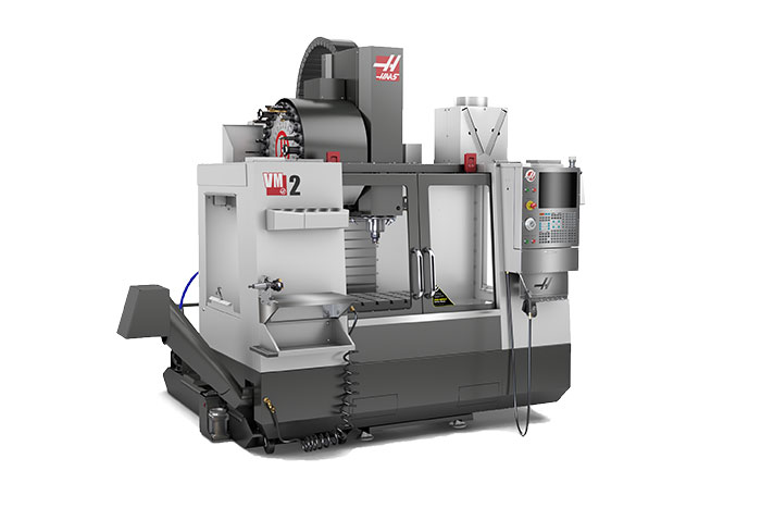
HAAS VM-2 is a 3-axis vertical machining center, or more precisely a vertical mold-making mill.
Technical characteristics:
Travels on X-Axis 762 mm
Travels on Y-Axis 508 mm
Travels on Z-Axis 508 mm
Spindle Nose to Table (~ max) 610 mm
Spindle Nose to Table (~ min) 102 mm
Max Weight on Table (evenly distributed) 1361 kg
Max Speed 12000 RPM
Designed for mold making, this mill keeps it’s precision even during the longer machining periods, while also being able to perform well in short duration serial production.
DMG CTX 310
Maximum diameter that can be processed by scraping – ø260mm
Maximum scraping length – 581mm
Maximum spindle speed – 5000 RPM
Maximum diameter of the rod that can fit in the spindle – ø52mm
Stroke Z axis – 455mm
Stroke X axis – 185mm
Number of tools on the tour -12
Number of driven tools – 6
Fast walking on the X axis – 20m / min
Fast walking along the Z axis – 30m / min
This machine is also characterized by the existence of a C axis

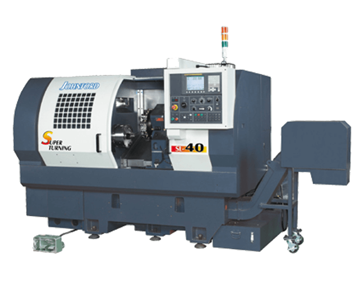
John Ford – SL 40
Maximum diameter that can be tightened – ø580mm
Maximum diameter that can be processed by scraping – ø450mm
Maximum diameter of the rod that can fit in the spindle – ø76.5mm
Maximum spindle speed – 4000 RPM
Number of tools on the tour – 12
Tool travel along the Z axis – 600mm
Tool travel along the X axis – 240
High speed machine – 20m / min
Milling Machine NVX 5100 2nd Generation
NVX 5100 2nd Generation
Best-ever high-precision vertical machining center
Max. X travels 1,050 mm
Max. Y travels 530 mm
Max. Z travels 510 mm
Max. table load 1,200 kg
Table length 1,350 mm
Table width 600 mm
Control & software alternatives
CELOS/MAPPS
Mitsubishi – MV1200-S – EDM
Maximum stroke on the X axis – 400mm
Maximum stroke along the Y axis – 300mm
Maximum stroke along the Z axis – 220mm
Possibility of placing the wire at a certain angle depending on the height of the piece – 15˚ at 200mm, or 30˚ at 87mm
Maximum dimensions of the preparation 810x700x215mm
Maximum preparation weight 500kg
Desk dimensions – 640x540mm
The diameter of the wire that can be used – 0.1-0.3mm
It has an automatic waste wire shredder

Wire EDM

Wire EDM (Electrical Discharge Machining) is a precision metalworking process used to produce complex shapes and extremely tight tolerances, especially in hard and hardened materials. The process is based on controlled electrical discharges between a thin wire electrode and the workpiece, removing material without any mechanical contact.
In our production process, we use the Mitsubishi MV1200 (Figure 1), a modern EDM machine designed for high precision, stability, and repeatability. This model is particularly well suited for manufacturing tools, molds, and precision engineering parts where conventional milling or turning cannot achieve the required quality or geometry.

Figure 1 – Mitsubishi MV1200 Wire EDM
Mitsubishi MV1200 in practice
The Mitsubishi MV1200 features a robust and thermally stable construction, precise axis control, and an advanced pulse generator. This combination enables an optimal balance between cutting speed and surface quality, even when machining thick or technologically demanding materials. Independent control of the upper and lower wire guides allows for tapered cuts and high geometric accuracy across the entire height of the workpiece. Automatic control of discharge parameters, wire tension, and flushing contributes to a stable process, reduced risk of wire breakage, and high repeatability of results, which is especially important in serial production.
Principle of wire EDM operation
During machining, a brass or coated wire continuously moves between the upper and lower guides, while the workpiece is submerged in deionized water. Electrical pulses between the wire and the workpiece cause controlled micro-erosion of the material along a precisely defined CNC tool path. Since there are no cutting forces, very hard materials can be machined without deformation or internal stresses.
Advantages of wire EDM
Wire EDM provides extremely high accuracy and excellent surface quality. Tolerances in the range of a few microns are standard, and the resulting surface finish often does not require additional finishing operations. A key advantage is the ability to produce sharp internal corners and complex contours that are not achievable with conventional cutting tools.
Applications of wire EDM
Wire EDM is most commonly used in the production of plastic injection molds, stamping tools, precision mechanical parts, gears, and hardened components with complex geometries. All electrically conductive materials can be machined, including tool and stainless steels, titanium, copper alloys, and tungsten carbide.
Conclusion
Wire EDM is an indispensable process in modern precision manufacturing. By using the Mitsubishi MV1200 machine, we ensure a high level of accuracy, consistent machining quality, and flexibility in producing technically demanding parts, with full process control and repeatable results.
HDDSMachining
Our new facility is openedOur new facility is opened.
We’re excited to announce that our new working environment is finally operational.
And we are glad that we are going to be able to offer our customers more production capabilities than before.
The construction of this 1000m2 building was realised in 2019-20 as a product of the development of our successful business during the previous years.
Our facility is equipped with modern CNC metal cutting machines.
We are continuing towards our goal of expanding machine processing capacity.
Supporting clients in their projects is our priority.


One of the most interesting types of production that we came across in the past period is the processing of hexagonal and square holes, which has a more popular term – broaching.
At the first sight this type of processing may look complicated, but is quite simple actually. The tool’s integral parts are the carriers and cutting bit that can have different shapes, depending of the desired shape of the technical hole.
On the photo bellow you may see an example of the finished piece:

For this piece we used a tool set from Garant Hoffmann Group.
Hexagonal, square, triangular, torx and so on are just a few most usable forms of this tool, as there are literally an infinite number of combinations.
Photo 2 shows a set of cutting bits for hexagonal processing, with sizes from 6 to 17 mm.
Cutting bit is assembled on the carrier which allows a free rotation of the axle and lathe processing. The tool is usually tilted for 1 degree which allows the cutting process.

The workpiece is prepared by pre-drilling a hole of the appropriate diameter (relative to the size of the hexagonal cutting bit), and then the edge is deburred in order to make more controllable cutting process.
The workpiece is tightening in the clamping head of the lathe and rotates as the tool approaches to it. At the moment of contact between the tool and the workpiece, they start rotating together and, due to the tilt mentioned above, cuts the tool’s profile.
It is interesting that in this type of processing, the chip has no way to get out of the technical hole, as the tool pushes it in front making chip remnant in case of the hole.

For this reason, a deeper hole is drilled in order to ensure that the hexagonal shape is of adequate depth, and the finish ends with another pass of a drill with slightly smaller diameter, which cleans the previously deposited chip and produces a technically correct piece.
It is also worth noting that this method of making hexagonal holes is fast, economical and with satisfied precision.
Materials that can be processed in this manner should be softer.
It is desirable to cool the cutting zone with cutting oil, or concentrated emulsion.